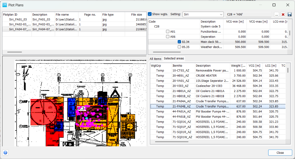
Use Plot Plans to place items and code-defined areas on a calibrated drawing. Open View > Drawings > Plot Plans with a project open. The window combines a plot-plan list, a code hierarchy, a drawing canvas and an item list. It can help you inspect item positions, review area boundaries and assign codes based on item centres of gravity.
The plot-plan list is at the upper left, the code hierarchy at the upper right, the drawing below on the left and the item list below on the right. Drag the dividers to adjust the available space. The coordinate labels and units follow the project settings. In the drawing planes, X is longitudinal, Y transverse and Z vertical; these correspond to LCG, TCG and VCG respectively.
Add and select a drawing
Right-click the plot-plan list and choose Add. Select a PNG, JPG, JPEG or BMP image. The image is stored with the project, together with its original file name and path. A plot-plan ID and description are initially generated from the file name. Select the required row to display its drawing. PDF and CAD files must first be converted to a supported image format.
Plotplan ID and Description identify the drawing. File name, Page no., File type, File size and File hash describe its source. Changing a file-name cell does not itself reload the image: use Update Image from File to read the file again from the stored path. Recheck calibration if the replacement image has a different size, crop or orientation.
Plane selects XY, XZ or YZ. Position specifies the coordinate of the drawing plane along the remaining axis: Z for XY, Y for XZ and X for YZ. Unit records the drawing unit. Use a consistent origin, direction and coordinate convention for the drawing, calibration points and project data.
Calibrate the drawing
Select an existing plot plan, right-click its row and choose Calibrate. Click a recognisable first point in the drawing and enter its model coordinates in the position dialog. Click a second point and enter its model coordinates. Choose two distinct points with known coordinates, preferably far apart for a reliable scale.
The two coordinate pairs refer to the axes of the selected drawing plane: X/Y for XY, X/Z for XZ and Y/Z for YZ. The calibration calculates model units per image pixel and the rotation, and stores the image and model reference coordinates with the plot plan. Check the result against another known point before using it to interpret item positions.
The list also exposes Image ref.1/2, Model ref.1/2, Scale, Rotation deg. and Is mirrored. These describe the image-to-model transformation. Use the calibration command for normal setup and check the plotted result after changing transformation values manually.
Use the mouse wheel over the canvas to zoom around the pointer. Drag an empty part of the drawing to pan. Clicking an item marker or a code box selects that object instead of starting a pan.
Define and display code areas
The code hierarchy lists project codes and their minimum and maximum coordinates, together with Factor, UnitWeight, Start and Stop. The coordinate limits define three-dimensional boxes. Check the codes you want to display on the drawing; only boxes relevant to the selected plane and position can be shown. Use the right-click commands to expand, collapse, check or uncheck branches.
Edit the coordinate bounds in the code table to define or adjust an area. These are project code values, not merely annotations on an image. Check all three axes even when the current drawing shows only two. A box can appear correct in one projection while having incorrect depth along the remaining axis.
Show overlapping boxes marks intersecting boxes in red for the selected code type and highlights the bounds involved. It checks three-dimensional volume overlap, including boxes within the same parent area. Shared boundaries alone are not overlaps. All boxes of that code type are checked, not only the currently checked boxes. Choose the command again to hide the markings; checked areas and item selection are preserved.
Show and select items
All items lists the items available through the current Plot Plans filter. Selected areas limits the list to the checked, displayed code boxes. Area tests use the item centre of gravity and all three coordinate bounds, including the minimum and excluding the maximum. They do not test whether the entire physical item fits inside a box.
Enable Show wgts. to display item markers on the drawing. The markers use the selected plane, the current filter and the visible areas. If no markers appear, check the drawing calibration, plane and position, checked areas, item coordinates and filter before assuming there are no items.
Selection in the item list is reflected in the drawing, and clicking a plotted item selects it in the list. Deselect All clears the item selection. Use Show Columns from the item-list menu to choose which fields are visible. Inspect the weight-column heading and project unit settings when interpreting the displayed values.
Filter and saved settings
Use the browse button beside the filter to edit the Plot Plans item filter. Clear Filter removes the active Plot Plans filter without deleting saved filters. The item list, plotted markers and displayed totals use the active filter. This is the Plot Plans filter, so check it separately from filters used in other windows.
Setting selects a saved Plot Plans view. The save button stores a named setting, including the selected plan and area/view configuration. Use separate setting names for views you want to keep. Close also remembers the active filter for the next visit.
Assign codes from underlying boxes
In All items, select physical items in the current subproject and choose Assign code from underlying boxes from the item-list right-click menu. Select a code type and hierarchy level in the assignment dialog, review the preview counts and then confirm the assignment. Items not eligible for assignment are left unchanged.
This command writes item codes and requires MultipleEdit permission for the selected code type. It is unavailable for the Selected areas tab and for a master-project instance view. Open the construction-unit subproject to update its physical items. After assignment, apply code mapping and summarise weights in the Items window as indicated by the program.
Saving and closing
Drawing additions, image updates, calibration and code-table edits are stored as they are performed. Code assignment is also a project-data change. Close stores the current view/filter state and closes the window; it does not undo these operations. Help and F1 open this topic.