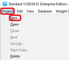
To start a new project, choose New… on the Project menu or press the New button on the toolbar: 
Project Info contains three tabs: General, Additional and Coordinates. Use them to enter project details, configure subprojects and define the reference coordinate system. Database ID and Project ID are required when creating a project. When viewing an existing project, the fields available for editing depend on your permissions.
General
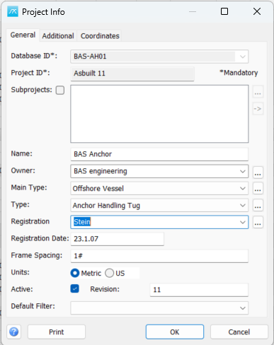
Database ID:
Identifies the project database. Select an existing database or enter a new database ID when creating a project. Creating a database requires the appropriate SQL Server permissions. The Database ID field is read-only when editing the current project.
Project ID:
Identifies the project within the database. The initial value for a new project is Master. A database can contain several projects, each identified by its Project ID.
Subprojects:
Select the checkbox to include subprojects. For an existing project, click the browse button (...) to select subprojects. The list shows the included subprojects. When creating a project, save it before adding subprojects with this button.
Instances and transformations:
Select a subproject in the list, then click the arrow button (->) to open its instance and transformation settings. The button is enabled when subprojects are selected. These settings allow you to configure instances of the selected subproject.
Name:
Enter a descriptive project name.
Owner:
Enter or select the owner. Click (...) to open the owner address library.
Main Type and Type:
Select the main project type and its subtype. The browse buttons (...) open the project type definitions.
Registration Pers. and Registration Date:
Enter or select the person registering the project and enter the registration date. The person browse button (...) opens the user address library.
Frame Spacing:
Defines the conversion between frame numbers and longitudinal positions. See Frame spacing below for syntax and examples.
Units:
Select Metric or US units for the project.
Active:
Select this checkbox to mark the project as active for listing in the Open Project window.
Revision:
Enter the project revision. If the project uses accumulated revisions, select a revision from the available list instead.
Default Filter:
Select a saved global filter for the project. The list contains the global filters available for the current project. A blank selection leaves the default filter unspecified.
Additional
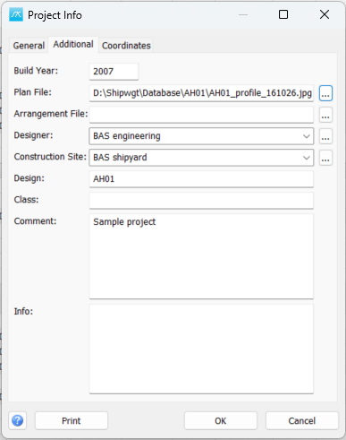
Build Year:
Enter the year the project was completed.
Plan File and Arrangement File:
Enter the drawing file paths or use the browse buttons (...) to select files. The current file selectors offer BMP, JPG, WMF, EMF, ICO, GIF, DXF and PDF files. Select the appropriate drawing for each field.
Designer:
Enter or select the designer. Click (...) to open the designer address library.
Construction Site:
Enter or select the construction site. Click (...) to open its address library.
Design:
Enter the design designation.
Class:
Enter the classification or class notation.
Comment:
Enter a project comment.
Info:
Enter additional project information. This field is separate from Comment.
Coordinates
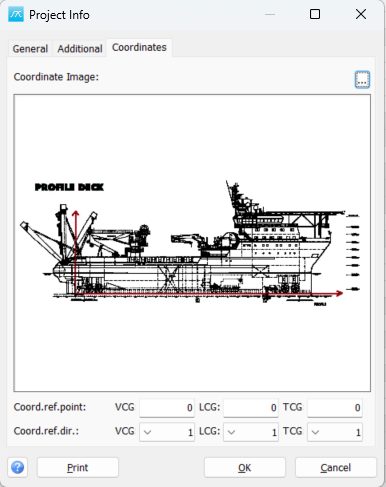
This tab contains the reference point, axis directions and coordinate image. The coordinate labels follow the labels configured in the application.
Coord. Ref. Point:
Enter the origin of the reference coordinate system in global coordinates. For the standard VCG, LCG and TCG labels, the entries correspond to the vertical, longitudinal and transverse directions respectively.
Coord. Ref. Dir.:
Select the sign for each reference axis: 1 keeps the positive direction of the global axis, and -1 reverses it.
Coordinate Image:
Click (...) to open the image dialog and choose an image illustrating the coordinate system. The selected image is displayed on this tab.
To display reference coordinates in the main window, use Show reference CoG on the Weight Groups menu or its toolbar button.
Buttons and help
Help / F1:
Click the question-mark Help button or press F1 to open this topic.
Print:
Open the project information report. This requires permission to output project information.
OK:
Save the project information and close the window.
Cancel:
Close the window without saving changes made in Project Info.
Frame spacing
Specify the frame spacing interval (∆) and the location where the spacing changes.
- The Aft Perpendicular is set at Frame number 0.
- If longitudinal spacing is constant, input only one ∆ value.
The syntax is:
∆1#FR1; ∆2#FR2; ∆n#FRn
- Where ∆n is the frame spacing from FRn-1 to FRn
- FRn is the frame number where the spacing changes, given in the order of increasing frame numbers
Example 1: For a ship with a constant frame spacing of, for instance, 0.6 meters, specify as follows:
0.6#
This creates a constant frame spacing system with the origin at zero.
Example 2:
For a ship with frame spacing of 0.7 meters up to frame number 10, 0.8 meters up to frame 120, and 0.7 meters further ahead, specify as follows:
0.7#10;0.8#120;0.7#
Additional interval changes can be added by appending frame number and interval pairs, separated by semicolons.
For example, if a new frame spacing of 0.5 meters is needed from Frame #135, add:
135;0.5#
The complete Frame spacing string would be:
0.7#10;0.8#120;0.7#135;0.5#
If the aft perpendicular does not align with frame number 0 (e.g., #0 and X=0 are not congruent), make the adjustment by setting ±<distance>;<frame spacing>. Here, <distance> is the measurement between X=0 and #0, and <frame spacing> is defined as above.
Example 3:
For instance, if X=0 resides in AP and #0 is located 0.2 meters ahead of AP (in the positive direction towards FP), and the frame spacing is as in Example 2. Then the frame spacing definition would be:
+0.2; 0.7#10;0.8#120;0.7#
Completing a new project
The following steps apply when creating a new project, rather than editing the information for an existing project.
Click OK when you have entered the necessary information.
Next, you'll be asked to specify the top-level weight group (post). In most cases, this will be "DISP Displacement".
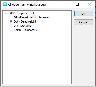
Select DISP Displacement and click OK.
The main parameter window will then appear, where you can fill in all available project details.
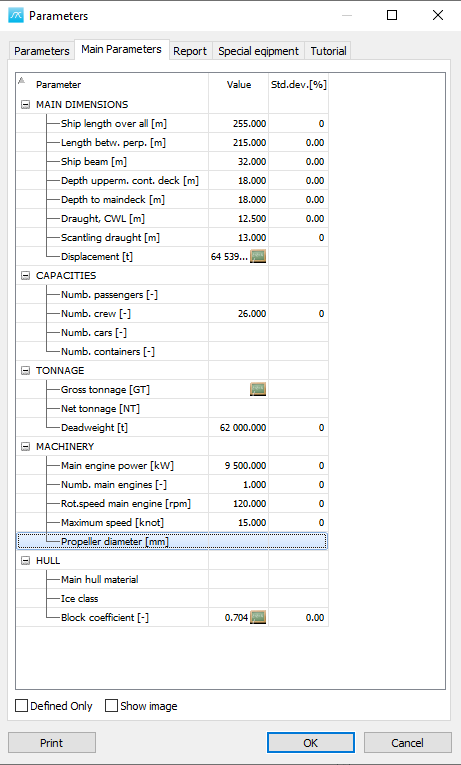
Click OK when you have entered the parameters you would like to store in the project.