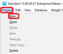
To start a new project, choose New… on the Project menu or press the New button on the toolbar: ![]()
This will bring up the Project Info window, this window has two tab sheets; General and Additional. In this window you can enter the available project information.
The fields Database ID, Project ID are mandatory, the others are optional.
Here's an overview of the available fields in the two different tabs:
General:
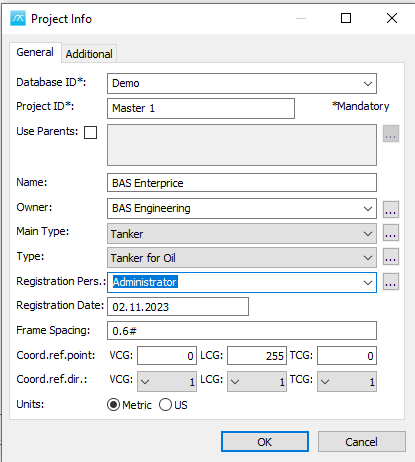
Database ID:
This field holds the name of the SQL database. It's crucial to note that once a project has been created, the ID cannot be altered. Keep in mind that a single database has the capacity to house multiple projects.
In case you possess the necessary SQL privileges to generate a new database, you can do so by entering a new name in this field. However, if you lack these privileges, you'll encounter an error message stating: "Could not execute SQL: CREATE DATABASE 'NewProjectName'". This indicates an attempt to create a new database, 'NewProjectName', without the required permissions.
Project ID:
This is the name of your current project. By default, it's set to "Master". It's crucial to note that once a project has been created, the ID cannot be altered.
![]() Important!
Important!
A project is defined by a database ID and a project ID. This means that you can store any number of projects on a single project-database.
Use Parents:
Check the box to make another project within the same database as the parent. Once selected, click the browse button ![]() to choose the parent project from the available options.
to choose the parent project from the available options.
A parent project, existing in the same database, serves as the source from which the current project inherits weight-related items.
All weight-related information is sourced from both the project and its parent project, affecting areas such as item dialog, main window, summaries, and reports. However, any changes made are exclusive to the current project and do not affect the parent project. Should you need to modify information in the parent project, it must be opened separately.
Name:
In this field, you can enter the name of the project. The maximum character limit for this field is 30.
Owner:
You can either type in the name of the project owner or choose from a list of previously registered owners in the dropdown menu. Alternatively, click the "Browse" button ![]() to access the Addresses library where you can register a new Owner in the Owner tab or choose one of the already registered owners. The maximum character limit for this field is 50.
to access the Addresses library where you can register a new Owner in the Owner tab or choose one of the already registered owners. The maximum character limit for this field is 50.
Main type:
Choose from the available options in the dropdown list for the main project type. Alternatively, click the "Browse" button to open the Project Types window.
Type:
You can select a project type from the dropdown list, or click the "Browse" button to open the Project Types window.
Registration pers.:
You can either type in the name of the registration person or select from the drop-down list. Alternatively, click the "Browse" button ![]() to access the Addresses library, where you can register a new user in the User tab or choose from the already registered users. The maximum character limit for this field is 50.
to access the Addresses library, where you can register a new user in the User tab or choose from the already registered users. The maximum character limit for this field is 50.
Registration date:
Enter the registration date using your preferred date format. The maximum length for this field is 10 characters.
Frame spacing:
Specify the frame spacing interval (∆) and the location where the spacing changes.
- The Aft Perpendicular is set at Frame number 0.
- If longitudinal spacing is constant, input only one ∆ value.
The syntax is:
∆1#FR1; ∆2#FR2; ∆n#FRn
- Where ∆n is the frame spacing from FRn-1 to FRn
- FRn is the frame number where the spacing changes, given in the order of increasing frame numbers
Example 1: For a ship with a constant frame spacing of, for instance, 0.6 meters, specify as follows:
0.6#
This creates a constant frame spacing system with the origin at zero.
Example 2:
For a ship with frame spacing of 0.7 meters up to frame number 10, 0.8 meters up to frame 120, and 0.7 meters further ahead, specify as follows:
0.7#10;0.8#120;0.7#
Additional interval changes can be added by appending frame number and interval pairs, separated by semicolons.
For example, if a new frame spacing of 0.5 meters is needed from Frame #135, add:
135;0.5#
The complete Frame spacing string would be:
0.7#10;0.8#120;0.7#135;0.5#
If the aft perpendicular does not align with frame number 0 (e.g., #0 and X=0 are not congruent), make the adjustment by setting ±<distance>;<frame spacing>. Here, <distance> is the measurement between X=0 and #0, and <frame spacing> is defined as above.
Example 3:
For instance, if X=0 resides in AP and #0 is located 0.2 meters ahead of AP (in the positive direction towards FP), and the frame spacing is as in Example 2. Then the frame spacing definition would be:
+0.2; 0.7#10;0.8#120;0.7#
Coord. ref. point:
By entering data for Coord. ref. point and Coord. ref. dir., a secondary coordinate system is defined. Coord. ref. point is the origin of the secondary coordinate system:
VCG: Global reference point in z-direction
LCG: Global reference point in x-direction
TCG: Global reference point in y-direction
Coord. ref. dir.:
Set the positive direction of the axis of the secondary coordinate system:
VCG: Sign for the z-axis. If positive upward 1, if positive downward -1
LCG: Sign for the x-axis. If positive foreward 1, if positive backwards -1
TCG: Sign for the y-axis. If positive toward starboard 1, if positive toward portside -1
![]() Tip: To activate the alternative coordinate system, select ‘Show reference CoG’ on the Weight Groups menu in the ShipWeight main dialog window. Alternatively click the ‘Show reference CoG’ button on the toolbar:
Tip: To activate the alternative coordinate system, select ‘Show reference CoG’ on the Weight Groups menu in the ShipWeight main dialog window. Alternatively click the ‘Show reference CoG’ button on the toolbar: ![]()
Units:
Choose between Metric or US units for the project.
Additional:
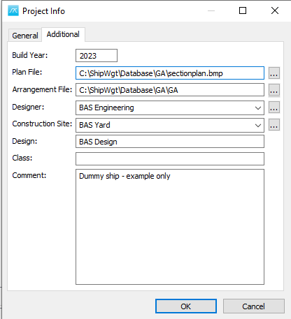
Build year:
This field represents the year when the project was completed.
Plan File:
This is where you specify the name and location of the section drawing file. Ensure that the location link does not exceed 255 characters in length. The drawing must be in either BMP or JPG format. Select the "Browse for location" button![]() to select the file location.
to select the file location.
Arrangement File:
Specify the name and location of the General Arrangement (GA) drawing file. Ensure that the location link does not exceed 255 characters in length. The drawing must be in either DXF or DWG format. Select the "Browse for location" button![]() to select the file location.
to select the file location.
Designer:
You can either type in the name of the project designer or choose from a list of previously registered designers in the dropdown menu. Alternatively, click the "Browse" button ![]() to access the Addresses library where you can register a new Designer in the Designer tab or choose one of the already registered designers. The maximum character limit for this field is 50.
to access the Addresses library where you can register a new Designer in the Designer tab or choose one of the already registered designers. The maximum character limit for this field is 50.
Construction Site:
You can either type in the name of the Construction Site or choose from a list of previously registered Construction Sites in the dropdown menu. Alternatively, click the "Browse" button to access the Addresses library where you can register a new Construction Site in the Construction SIte tab or choose one of the already registered Construction Sites. The maximum character limit for this field is 50.
Design:
This field represents the name of the design. The maximum character limit for this field is 255.
Class:
This field can hold the class society with its notation. The maximum character limit for this field is 255.
Comment:
This field allows you to add comments. You can enter up to 255 characters.
Click OK when you have entered the necessary information.
Next, you'll be asked to specify the top-level weight group (post). In most cases, this will be "DISP Displacement".
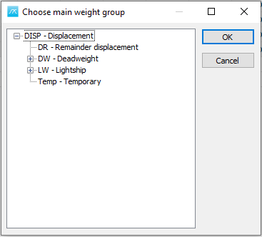
Select DISP Displacement and click OK.
The main parameter window will then appear, where you can fill in all available project details.
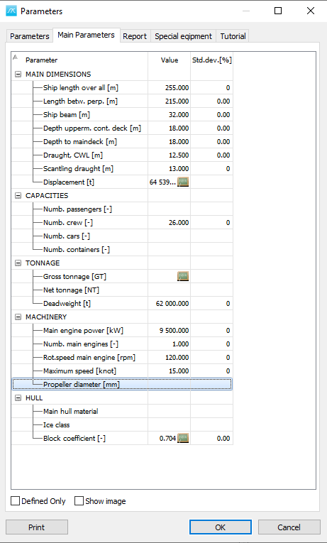
Click OK when you have entered the parameters you would like to store in the project.