To start a new project, choose New… on the Project menu or press the New button on the toolbar: ![]()
The Project Info window appears. Now you can enter project data for your new project.
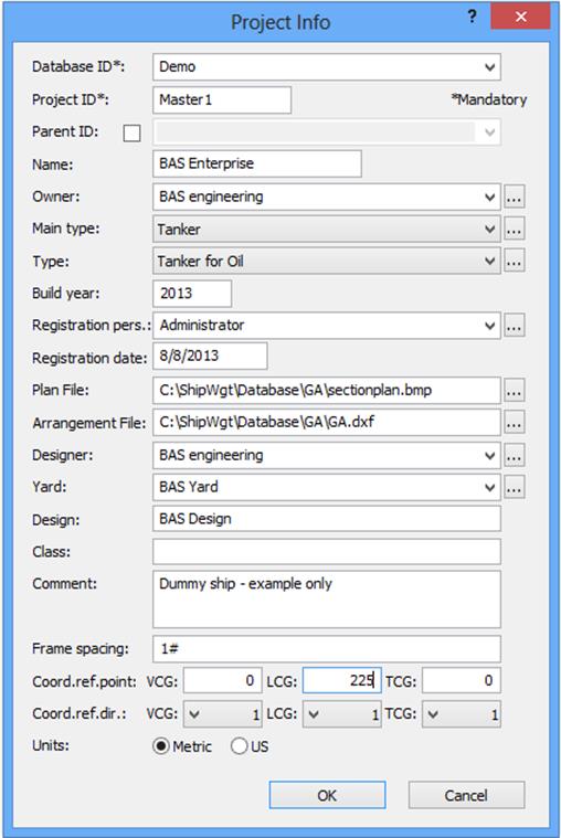
The fields Database ID, Project ID are mandatory, the others are optional. The available fields are:
Database ID: |
This is the name of the SQL database. The ID cannot be changed after the project has been created. Please note that one database can contain several projects
|
Project ID: |
The name of the current project. Default: Master
From version 7.5 and onwards, a project is defined by a database ID and a project ID. This means that you can store any number of projects on a single project-database.
|
Parent ID: |
The name of an existing project (in the same database) from which the current project will inherit weight items. All weight information read from the database is read from the project and the parent project, i.e. item dialog, main window, summaries and reports. All weight information that is written is written to the project only. The weight items inherited from the Parent-project cannot be edited from within the current project. To change information in the parent project, the parent project must be opened separately.
|
Name: |
The name of the project needs to be maximum 30 characters.
|
Owner: |
Enter the name of the project owner or select one of the previously registered project owners from the dropdown list. Alternatively, press the Browse-button
|
Main type: |
Select one of the available Main Project Types from the dropdown list, or use the Browse-button to open the Project Types window.
|
Type: |
Select one of the available Project Types from the dropdown list, or use the Browse-button to open the Project Types window.
|
Build year: |
Year of completion of the project
|
Registration pers.: |
Maximum 50 characters.
|
Registration date: |
Maximum 10 characters.
|
Plan File: |
The name and path of the section drawing file. The drawing must be of type bmp or jpg. Maximum 255 characters.
|
Arrangement File: |
The name and path of the GA drawing file. The drawing must be of type dxf or dwg. Maximum 255 characters.
|
Designer: |
The name of the project Designer, maximum 50 characters.
|
Construction Site: |
The name of the Construction Site of the project, maximum 50 characters.
|
Design: |
The name of the design, maximum 255 characters.
|
Class: |
The name of the class, maximum 255 characters.
|
Comment: |
A comment field, maximum 255 characters.
|
Fill in the appropriate frame spacing interval (∆) and location where the spacing changes. Aft Perpendicular is set at Frame number 0.
If longitudinal spacing is constant, input only one ∆ value.
The syntax is:
∆1#FR1; ∆2#FR2; ∆n#FRn
Where ∆n is the frame spacing from FRn-1 to FRn FRn is the frame number where the spacing changes, given in the order of increasing frame numbers
Example 1: A ship with constant frame spacing of e.g. 0,6 m. is specified as following:
0.6#
This will create a constant frame spacing system with the origin in zero.
Example 2: A ship with a frame spacing of 0.7 m. up to frame number 10, 0.8 m. up to frame 120 and 0.7 m. further ahead is specified as following:
0.7#10;0.8#120;0.7#
If more interval changes are required, simply add to the Frame spacing string, extra pairs of frame number and the new interval, as following: - if at Example 2 a new frame spacing (0.5 m) is required from Fr.#135, add to the previous Frame spacing string the pair 135;0.5#
Note the semicolon between the frame number and the frame spacing.
The complete Frame spacing string should now be: 0.7#10;0.8#120;0.7#135;0.5#
If aft perpendicular does not match frame number 0 e.g. #0 and X=0 are not congruent, this is adjusted by setting ±<distance>;<frame spacing> where <distance> is the distance between X=0 and #0 and <frame spacing> is frame spacing defined as above.
Example 3: X=0 resides in AP and #0 is located 0.2 meter ahead of AP (positive direction towards FP). Frame spacing is as in Example 2. Frame spacing definition would then be:
+0.2; 0.7#10;0.8#120;0.7#
|
|
Coord. ref. point: |
By entering data for Coord. ref. point and Coord. ref. dir., a secondary coordinate system is defined. Coord. ref. point is the origin of the secondary coordinate system: VCG: Global reference point in z-direction LCG: Global reference point in x-direction TCG: Global reference point in y-direction
|
Coord. ref. dir.: |
Set the positive direction of the axis of the secondary coordinate system: VCG: Sign for the z-axis. If positive upward 1, if positive downward -1 LCG: Sign for the x-axis. If positive foreward 1, if positive backwards -1 TCG: Sign for the y-axis. If positive toward starboard 1, if positive toward portside -1
|
Click OK when you are done.
Next you are asked to specify the top-level weight group (post). In most cases this will be Lightship LW.
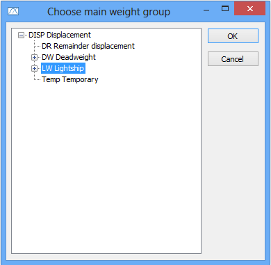
Select LW Lightship and click OK.
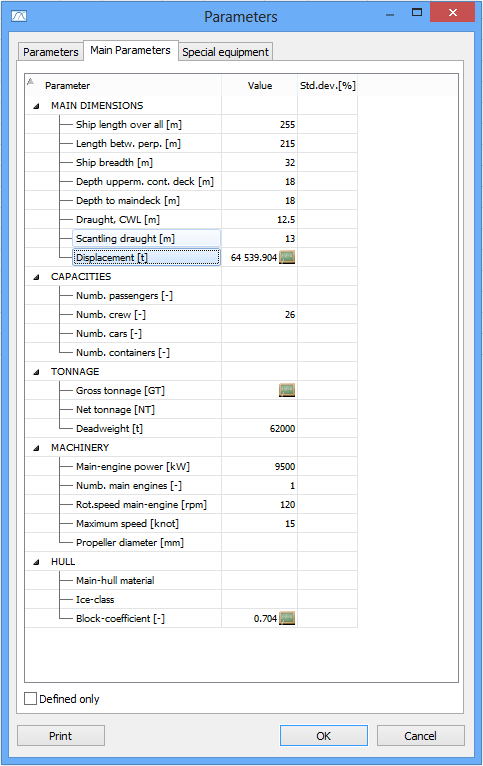
Next the main parameter window pops up, and you should fill in all the project particulars that are available.